|
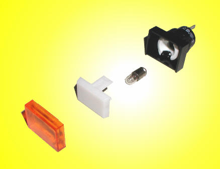
1.) Install the annunciator lights & switch in your instrument panel.
A.) Drill two holes for the lights, (0.625" dia.). The
lights measure 0.705" x 0.95", and protrude 0.35".
B.) Install the switch. Drill a 0.275" dia. hole.
B.) Affix the proper low fuel quantity lettering.
Right & Left Tank Instrument
Panel Lettering

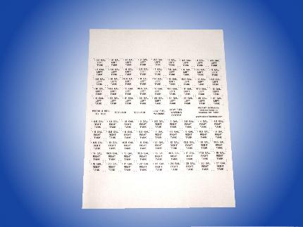
Lettering can be easily inserted in the light's lens!
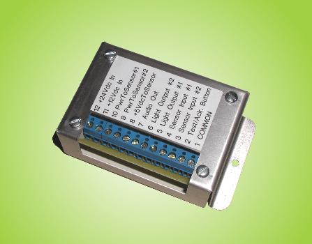
2.) Install the electronics.
A.) The electronics enclosure measures 3.5" x 2.25" x 1.25". Find an appropriate
spot under the instrument panel and install the enclosure using two #6-32 screws.
The centers of the mounting screws are 3.625" apart. Easy
wiring instructions are included!
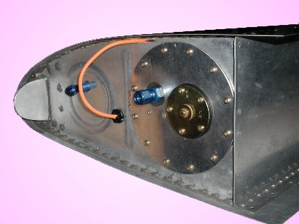
3. Find the proper location for the sensor.
A.) Position your fuel tank in the approximate "level flight
position".
B.) Temporarily attach a clear plastic hose to the fuel tank drain cock.
C.) Fill the tank (with WATER to be safe) to your pre-selected, low
fuel alarm quantity.
D.) Position the hose so that the top of the liquid in the hose,
is closest to your
internal fuel tank pick-up point.
E.) Mark the location for your sensor, near the top of the liquid
level in the hose.
Location #1
An Alternate Location

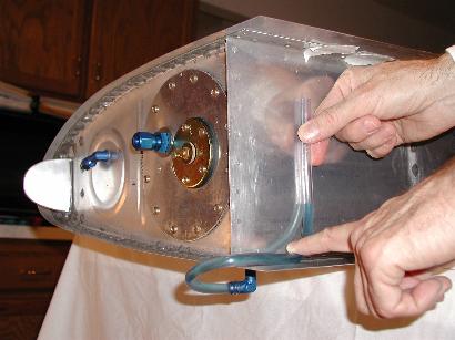
(Coloring had been added to the water for
photograph clarity)
This gentleman has chosen a 3.0 Gallon alarm level for his right RV-6 tank.
It is exactly 20 minutes of flight left at
9.0 Gal/Hr.
4.) Install the optical sensors in your fuel tanks.
See how to install the sensor.
Sensor
Installation
SENSOR DIMENSIONS
Sensor measures 0.75"
across flats of nut on the outside of the tank
The sensor protrudes
into the tank approximately 19.05mm (0.75 inches) max.
(Mount the sensor only horizontally, or vertically pointing up. The
reason for this is because you do not want to have any fluid drops on the end of
the sensor when there is no liquid present. This may give false readings.)
CAUTION!
DO NOT put the sensor wires in any liquid, even for testing the
system! The wires may not be totally liquid proof on the outside of the
sensor.
ONLY dip the tip of the sensor in liquid for testing the system. Be sure
not to scratch the tip of the sensor when handling it.
D.) Connect the sensor cables to the electronics.


"A VIEW FROM THE INSIDE THE TANK"
User applied a small amount of "Proseal Sealant" (not shown)
on the outside of the tank.
The 1/4NPT bung is also not showing in these photos. This photo is with
our older sensor.
It used an internal nut. We have since upgraded the sensor, so you
do not need an internal nut now.


|
